4. Instruments
4.1. Pre-configured instruments
The following optical cameras are available in THELI:
| Instrument Name | # chips | Remarks |
|---|---|---|
| ACAM@WHT | 1 | |
| ALFOSC@NOT | 1 | |
| ALTAU16M@VYSOS06 | 1 | |
| AltaU42_LOWRES@ASV | 1 | |
| AltaU42_HIGHRES@ASV | 1 | |
| ApogeeAlta@PROMPT4 | 1 | |
| ApogeeAlta@PROMPT5 | 1 | |
| CFH12K@CFHT99 | 12 | |
| CFH12K@CFHT | 12 | |
| DECam@CTIO | 62 | |
| EFOSC2@ESO3.6m | 1 | |
| EFOSC_2x2@ESO3.6m | 1 | |
| EMMI_BIMG@NTT | 1 | |
| EMMI_RILD@NTT | 1 | |
| ENZIAN_CAS@HOLI_1M | 1 | |
| FORS1_1CCD@VLT | 1 | Old configuration |
| FORS1_2CCD@VLT | 2 | New configuration |
| FORS2_1CCD@VLT | 1 | Old configuration |
| FORS2_2CCD@VLT | 2 | New configuration |
| GMOS-N-EEV-3port@GEMINI | 3 | 2x2 binning |
| GMOS-N-EEV-6port@GEMINI | 3 | 2x2 binning |
| GMOS-S-EEV@GEMINI | 3 | 2x2 binning (old EEV detectors) |
| GMOS-S-HAM@GEMINI | 3 | 2x2 binning (new Hamamatsu detectors, as of July 2014) |
| GOODMAN@SOAR | 1 | 1x1 and 2x2 binning |
| GPC1@PS1 | 64 | |
| GROND_OIMG@MPGESO | 1 | |
| IMACS_F2_OLD@LCO | 8 | |
| IMACS_F2_NEW@LCO | 8 | |
| IMACS_F4_OLD@LCO | 8 | |
| IMACS_F4_NEW@LCO | 8 | |
| LAICA_2x2@CAHA | 4 | |
| LAICA@CAHA | 4 | |
| LBC_BLUE@LBT | 4 | |
| LBC_RED@LBT | 4 | |
| LDSS3@LCO | 2 | |
| LORRI@NewHorizons | 1 | |
| MEGAPRIME@CFHT | 36 | |
| MEGAPRIME_ELIXIR@CFHT | 36 | ELIXIR pre-processing |
| MEROPE@MERCATOR | 1 | |
| MOSAIC-I_old@KPNO_0.9m | 8 | Old configuration (before Aug. 2010) |
| MOSAIC-I_old@KPNO_4.0m | 8 | Old configuration (before Aug. 2010) |
| MOSAIC-II_8@CTIO | 8 | 8-channel mode |
| MOSAIC-II_15@CTIO | 8 | 16-channel mode, 1 dead (after 2009-03) |
| MOSAIC-II_16@CTIO | 8 | 16-channel mode (before 2009-03) |
| MOSCA_2x2@NOT | 4 | |
| OASIS4x4@WHT | 1 | |
| OASIS@WHT | 1 | |
| OMEGACAM@VST | 32 | |
| PFC_old@WHT | 2 | Decommissioned |
| PFC_new@WHT | 1 | As of January 2013 |
| SDSS | 1 | Download SDSS FITS images and process them |
| SOI@SOAR | 2 | |
| SuprimeCam_200101-200104@SUBARU | 9 | One chip dead |
| SuprimeCam_200105-200807@SUBARU | 10 | |
| SuprimeCam_200808@SUBARU | 10 | New red-sensitive detectors |
| SuprimeCam_200808_SDFRED@SUBARU | 10 | New red-sens. det., SDFRED pre-processing |
| SuSI2_2x2@NTT | 2 | |
| SuSI2old_2x2@NTT | 2 | |
| VIMOS@VLT | 4 | |
| WFC@INT | 4 | 1x1 and 2x2 binning |
| WFC_IPHAS@INT | 4 | 1x1 binning, for IPHAS preprocessed data |
| WFI@AAT | 8 | |
| WFI@SSO_40inch | 7 | |
| WFI@MPGESO | 8 | |
| Y4KCam@CTIO | 1 |
The following infrared cameras are available in THELI:
| Instrument Name | # chips | Remarks |
|---|---|---|
| FLAMINGOS2@GEMINI | 1 | |
| FourStar@LCO | 4 | |
| GROND_IRIM@MPGESO | 1 | |
| GSAOI@GEMINI | 4 | |
| HAWKI@VLT | 4 | |
| INGRID@WHT | 1 | |
| ISAAC@VLT | 1 | |
| LIRIS_POL@WHT | 4 | |
| LIRIS@WHT | 1 | |
| MMIRS@LCO | 1 | |
| MOIRCS@SUBARU | 4 | |
| NACOSDI@VLT | 1 | |
| NEWFIRM@CTIO | 4 | |
| NICS@TNG | 1 | |
| NICI@GEMINI | 2 | |
| NIRI@GEMINI | 1 | |
| NOTcam_highres@NOT | 1 | |
| NOTcam_lowres@NOT | 1 | |
| Omega2000@CAHA | 1 | |
| OSIRIS_F3@SOAR | 1 | |
| OSIRIS_F7@SOAR | 1 | |
| OSIRIS@GTC | 1 | |
| PISCES@LBT | 1 | |
| SOFI@NTT | 1 | |
| SPARTAN@SOAR | 4 | |
| TRECS@GEMINI | 1 | mid-infrared |
| VIRCAM@VISTA | 16 | |
| VISIR@VLT | 1 | mid-infrared |
| WIRCam@CFHT | 4 |
4.2. Setting up a new instrument
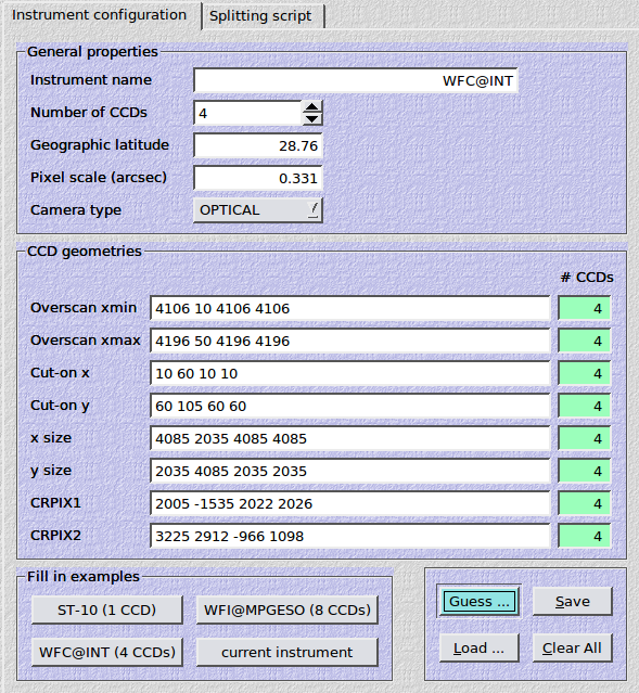
If your instrument is not contained in the pre-defined lists of instruments, you can include it in the dialog. For a camera with 4 CCDs it would like this:
4.2.1. Automatic creation
Configuring a new instrument for THELI is really easy. THELI can guess the chip geometries including overscan regions based on a well-exposed flat field (illumination level: 20-30 kADU). For this purpose an edge-detection algorithm is used. Just click on the blue Guess… button and select a suitable flatfield exposure. This can be a simple FITS image or, in case of a multi-chip camera, a multi-extension FITS file. In the latter case all extensions will be probed.
DSLR RAW format is also supported. In this case a simpler algorithm is used that works with any image.
Note
Fields that remain blank after this process must be filled in manually. You should check that the automatically determined values make sense, in particular overscan regions. For cameras with incomplete or ill-defined FITS headers the reference pixel should be checked as well.
4.2.2. General properties
Fields are self-explanatory.
Instrument name:
Stick to the Instrument@Observatory or Instrument@Telescope scheme. The name of the instrument chosen must be unambiguous. THELI will complain later on if it encounters two instruments with the same name.
4.2.3. CCD geometries
In this section the detector layout is defined. For multi-chip cameras you must enter a blank-separated list of values in each field, one number for each detector. At the right end you get some visual feedback: the counter turns green when you hit the same number of entries as specified in the Number of CCDs field above. For cameras with more than a half a dozen detectors this is quite useful. If you are uncertain how this should look like, try the automatic approach, or fill in some of the examples, or select one of the pre-configured instruments (the Load… button).
The fields are as follows:
- Overscan xmin: The leftmost pixel of the overscan region. If the detector has no overscan, then enter a zero.
- Overscan xmax: The rightmost pixel of the overscan region. If the detector has no overscan, then enter a zero.
- Cut-on x: The first pixel in x-direction that receives light.
- Cut-on y: The first pixel in y-direction that receives light.
- x size: The number of pixels in x-direction receiving light.
- y size: The number of pixels in y-direction receiving light.
- CRPIX1: The x-coordinate of the astrometric reference pixel.
- CRPIX2: The y-coordinate of the astrometric reference pixel.
Warning
The parameters entered here must reflect the chip status after the data run through the splitting script, as the latter will rotate or flip images if you entered a non-zero transformation code.
Note
- Do not confuse x|y size with the coordinate of the last pixel receiving light on the x|y axis.
- Your choice of the first six parameters (overscan, cut-on and size) does not need to reflect the actual physical properties of the detector. For example, if your overscan region covers pixels 1 to 50, but you think that only pixels 20 to 45 are well-behaved, then you would use the latter values in the camera configuration. Same for the detector area that receives light.
- The reference pixel does not need to be accurate. The astrometric solution will determine it precisely. In exceptional cases it can be helpful if you get it right within, say, 10 arcseconds, but usually errors as large as several arcminutes are recovered easily.
- You must save the instrument configuration before proceeding to the creation of the splitting script.
- If you are an amateur astronomer and use a chip with Bayer matrix, then x|y size must consist of even numbers (see Bayer matrix)
Once the instrument has been created, it can be selected from the list of user-defined instruments in the Initialise section.
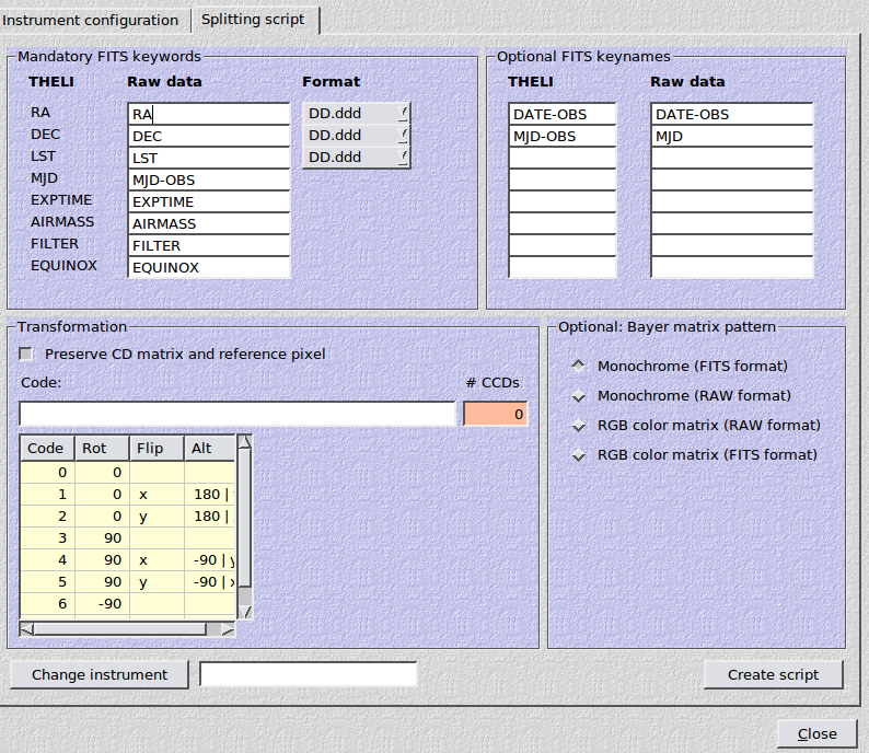
4.3. Creating the splitting script
In the previous section you told THELI about the geometries of your detectors. In addition, you have to provide information about the raw data format itself, such that it can be converted into something THELI can read and make sense of. This is done by an instrument-specific splitting script, which you should define immediately after finalising and saving the instrument configuration. Just switch to the Splitting script tab menu to invoke the corresponding dialog:
The splitting script will do several things to your data:
In case of a multi-chip camera data is mostly stored in a multi-extension FITS file. The script will break this FITS up and write individual 32bit floating point FITS files for each detector, such that full advantage can be taken from parallel processing. The chip number will be introduced into the file name just before the suffix. For example, if the file image.fits contains 4 extensions, the individual files will be named:
image_1.fits
image_2.fits
image_3.fits
image_4.fits
The script will write a very basic and compact FITS-compliant header, containing only the essential information about the data itself and a valid WCS solution.
If desired, all chips in the detector mosaic can be brought to the same orientation.
Amateur astronomers with color-coded detectors using a Bayer matrix have to specify if their data is in DSLR RAW or FITS format. In the latter case one must indicate how the Bayer matrix is encoded. This can involve some trial and error. See also the section about the Bayer matrix below.
4.3.1. Mandatory FITS keywords
You must tell THELI the names of the FITS keywords in your data, such that your raw FITS header can be properly translated into a THELI-conform header. For some keys such as RA, DEC and LST you must define the format as well.
EXPTIME
For the exposure time keyword you can either specify a single FITS keyword, or in case of near-infrared cameras, two comma-separated keywords, e.g.:
DIT,NDIT
where DIT represents the individual detector integration time, and NDIT the number of such exposures averaged for the final image. The resulting image will be multiplied by NDIT in order to maintain a consistent background level (otherwise exposures with different NDITs cannot be processed/combined consistently).
FILTER
If two filter wheels are present in the instrument, you can specify two comma-separated filter keywords, e.g.:
FILTER1,FILTER2
The resulting FILTER keyword in the FITS header will then read:
FILTER1+FILTER2
4.3.2. Optional FITS keywords
You can propagate up to 8 other FITS keywords from your raw data into the THELI conform headers. You must provide an unambiguous key name for the THELI header, and the name of that key in the raw data. If the key name for the THELI header is longer than 8 characters, it will be truncated without warning.
4.3.3. Transformation
Preserve CD matrix and reference pixel
If your data come with a valid astrometric WCS header, you should leave this setting activated. If you unmark it, THELI will re-orient the CD matrix in the FITS headers such that North is up and East is left. In any case the precise (or correct) orientation will be determined during the astrometric part of the reduction.
Code
Often the chips in multi-chip cameras have different orientations. While this is no problem for THELI, it can be easier to work with the data if the orientation of all chips is identical, in particular if the data have to be eyeballed frequently. You must enter a blank separated list of numbers for the transformation code, one number for each detector. If no transformation should be done, then enter zeros. If a rotation and flip are combined, then the rotation is performed first. Positive rotation angles are counted counter-clockwise. The coding is as follows:
| Code | Rotation | Flip |
|---|---|---|
| 0 | 0 | |
| 1 | 0 | x |
| 2 | 0 | y |
| 3 | 90 | |
| 4 | 90 | x |
| 5 | 90 | y |
| 6 | -90 | |
| 7 | 180 |
Warning
If non-zero transformation codes are entered, the chip geometries defined previously must reflect the status AFTER any flipping or rotation has been applied.
4.3.4. Bayer matrix
All professional instruments have monochrome CCDs. If you are a scientist, leave the default selection unchanged and ignore the rest of this section.
If you are an amateur astronomer, and you work with DSLR CMOS chips (data in RAW format) or CCDs with a Bayer color matrix imprinted on the chip (data in FITS format), then select the option describing your camera. If your data is in FITS format, then you must also specify the color coding of the Bayer matrix as it is usually not declared in the FITS header. If you do not know the encoding of the matrix this requires some trial and error.
Note
If you use a CCD with Bayer matrix and the data are in FITS format, then the Bayer matrix coding also depends on the settings for the CCD geometries, in particular Cut-on x|y. In addition, x|y size must be made of even numbers, as otherwise the de-bayering later on will not work correctly.
4.4. THELI FITS headers
This is a short primer for the THELI FITS header (and FITS headers in general). The FITS header contains some basic information about the data, encoded in keywords. After running the splitting script it will look like this:
SIMPLE  =                    T / Fits format
BITPIX  =                  -32 / bits per pixel
NAXIS   =                    2 / single image
NAXIS1  =                 2048 / x size
NAXIS2  =                 4092 / y size
BSCALE  =                  1.0 / pixel scale factor
BZERO   =                  0.0 / pixel value offset
CTYPE1  = 'RA---TAN          ' / WCS coordinate type
CTYPE2  = 'DEC--TAN          ' / WCS coordinate type
CRPIX1  =              1092.00 / WCS Coordinate reference pixel
CRPIX2  =              2136.00 / WCS Coordinate reference pixel
CD1_1   = -6.61111e-05         / Change in RA  at CRPIX along 1st axis
CD1_2   = 0.0                  / Change in RA  at CRPIX along 2nd axis
CD2_2   = 6.61111e-05          / Change in DEC at CRPIX along 2nd axis
CD2_1   = 0.0                  / Change in DEC at CRPIX along 1st axis
CRVAL1  =  246.41666667        / RA at CRPIX
CRVAL2  =  -24.53870000        / DEC at CRPIX
RADECSYS= 'FK5               ' / Coordinate system for equinox (FK4/FK5/GAPPT)
FILTER  = 'B/99              ' / Name of filter
OBJECT  = 'IC4603            ' / observed target
AIRMASS =             1.357000 / (average) Airmass during observation
EXPTIME =               600.00 / effective exposure time
EQUINOX =              2000.00 / Equinox of coordinates
IMAGEID =                    1 / Chip Number
GABODSID=                  821 / Obs. date in days since 31/12/1998
EISID   =                    0 / no comment
ZP      =            -1.000000 / photometric zeropoint
COEFF   =             1.000000 / photometric extiction coefficient
DATE-OBS= '2010-05-12T02:02:26.989'
DUMMY1  =                    0 / Dummy for adding new FITS cards later
...
DUMMY50 =                    0 / Dummy for adding new FITS cards later
HISTORY
...
END
Herein, the CD matrix (the CDi_j elements) encode the sky position angle, the pixel scale, and a possible flipping. CRVAL1 and CRVAL2 are the right ascension and declination, respectively. A list of 50 DUMMY keywords is introduced as well, they will be partially replaced by more meaningful values during data reduction.
Warning
You should never tamper with FITS headers if you do not know what you are doing. And even if you know what you are doing, it is a very smart idea to create a backup copy before you touch the headers.