7. PREPARATION
This section is focused on preparing the raw data such that THELI can digest it. You can automatically sort the raw data, have to modify the fits headers, and in case of multi-chip cameras split the images into individual chips. Lastly, multi-chip data can be redistributed to different hard disks for faster processing.

7.1. Sort data using FITS key
If the scientific data and their corresponding calibration files are all mixed up, then you can attempt to identify different image types based on the value of a certain FITS keyword, e.g. the OBJECT key.
All images belonging to one category will be collected in a correspondingly named sub-directory. All other images that remain unmatched are assumed to be target observations and will be put in a sub-directory called SCIENCE.
7.1.1. Parameters

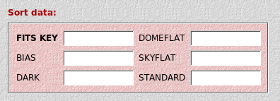
- FITS KEY: The keyword that identifies the data type
- BIAS: The string for a bias
- DARK: The string for a dark
- DOMEFLAT: The string for a domeflat
- SKYFLAT: The string for a skyflat
- STANDARD: The string for a standard star field
7.1.2. Check the sorting
After the data have been sorted, you should go into the individual sub-directories and run the following command in a console to verify data consistency (possibly adjusting the FITS keyword names)
dfits *.fits | fitsort EXPTIME FILTER OBJECT DATE-OBS
In this way you can easily see if e.g. a flat-field slipped into your biases, or a bias into your SCIENCE directory.
Another very useful command to check for outliers or bad images in the BIAS, DARK and FLAT directories is to look at basic image statistics:
imstats *.fits
If you cannot find these binaries, then you did not include THELI’s binary directory in your PATH variable (details).
Note
No sorting with respect to various filters is done. If you e.g. took flat fields in UBVRI filters, then all these flats will be put into the same FLAT directory. You must redistribute them manually.
Warning
This task relies on the integrity of the chosen FITS header keyword. If a flat is accidentally identified as a bias, then it will be put in the BIAS sub-directory etc. No further automatic consistency checks are performed by THELI. You still have to make sure that images end up in the correct sub-directories (see above for some helpful commands).
7.2. Split FITS / correct header
The main job of this task is to split multi-extension FITS files into the single chips, thus allowing for parallel processing. It also writes a new FITS header conform with the THELI pipeline. If single-chip images are provided, only the FITS header will be updated. Optionally, a crosstalk correction can be applied, and the image can be renamed.
This task will be applied to all sub-directories that have been specified in INITIALISE. If a master calibration file (bias, flat or dark) is found, then the corresponding directory will be skipped. THELI will try to correct all other files present. If a FITS image is found that was run through this step before (judging from certain header information), then it will be skipped.
At this point THELI will also replace the following characters in the file names and in the FILTER header keyword with underscores (‘_’):
$ , | " ' ; [ ] ! % / ( )
Warning
Only uncompressed FITS images, and no other files, should be present in the directory in which you attempt splitting. Otherwise an error will be returned, which may or may not have further consequences during processing.
7.2.1. Parameters

- Rename file to FITS key: The raw images can optionally be renamed to the string value of an arbitrary FITS keyword. This is useful if the software running at the telescope does not assign an unambiguous name to the file, but only to a certain header keyword.
- Normal crosstalk: Typical for CCDs and near-IR HAWAII detector arrays with several readout quadrants. Bright sources cause a ghost image in the other readout quadrants. You must specify the amplitude of the effect.
- Row crosstalk: Typical for CCDs and near-IR HAWAII detector arrays with one or several readout quadrants. The rows or columns going through a bright source have an enhanced background level (banding). The same rows in other readout quadrants can be affected, too. You must specify the amplitude of the effect.
- Multi crosstalk: Typical for HAWAII-2 detectors with their larger number of readout stripes. Bright sources leave ghost images in the other readout sections. You must specify the number of readouts. This task will calculate the median of all readouts and subtract it from each readout.
Crosstalk amplitudes can range from very small (0.0001) to very large (a few percent of the brightness of the source). THELI makes no assumptions about the crosstalk amplitude for the various instruments, which means you have to figure it out yourself through trial-and-error. When the crosstalk becomes invisible in the coadded image, then you got it right.
Note
The crosstalk amplitude must be a negative number if bright sources cause dark crosstalk features.
Note
The crosstalk correction assumes that the crosstalk amplitude is the same for all readout quadrants. This is commonly the case for HAWAII-1 detectors with 4 readout sections, but can be different for HAWAII-2 arrays with multiple readouts. In the latter case crosstalk correction will be incomplete with THELI.
Note
Crosstalk correction across different physical CCDs (e.g. a ghost image of one detector shows up in another) is not yet supported in THELI.
7.3. Create links
This section is not of interest for you if
- you reduce data from a camera with less than 2-4 CCDs
- you use 4 CPUs or less and have a reasonably fast hard disk
- your disks are in a RAID configuration appearing as one single disk
- you are a beginner with THELI or not familiar with how the Linux file-system works
7.3.1. How it works
If you work on a multi-core machine with several hard disks that you can address explicitly, then you can fully exploit THELI’s parallel mode.
The working principle is that different chips are processed by different CPUs on different hard disks, minimising I/O traffic on a single hard disk. This task will distribute the images taken with different CCDs to separate hard disks. At the same time a link structure is established that makes all the data appear to reside within the normal THELI directory tree.
7.3.2. What you have to do
Chips going to scratch: In this field provide a blank separated list of the chips you want to move to one scratch directory. For example, you are working on a camera with 8 CCDs using a machine with 4 CPUs and 4 hard disks. Then you would enter in this field the string “1 5” (without the quotes).
Scratch directory: This is the directory on the first hard disk where chips 1 and 5 go. You do not need to establish a directory tree in those scratch directories. All files end up in the same place, but are uniquely identified through the link system pointing to the various categories (bias, flat etc).
THELI will loop over all data sub-directories found in the Initialise section. Once done with chips 1 and 5, repeat the same for chips 2 and 6, and so on.
Note
The linked file system must be created after splitting the data.